Schneider ATV650D22N4 Variable Speed Drive Installation and Commissioning Guide
Time:2026-10-27 Browse: 4
Schneider ATV650D22N4 Installation Guide for 22 kW Motor Systems
The Schneider ATV650D22N4 variable speed drive is a 22 kW (30 hp) Altivar Process drive designed for three-phase 380–480 V motor applications. Reliable installation depends on correct power connections, adequate heat dissipation, accurate motor data entry, and a verified control strategy. For process pumps, fans, and other industrial equipment, commissioning should confirm that the drive responds correctly to local commands and PLC Controller signals before the machine enters normal service.
The ATV650D22N4 has an IP55 enclosure rating and integrated EMC filtering. These features support installation in demanding industrial environments, but they do not eliminate the need for suitable cable routing, grounding, and environmental assessment.
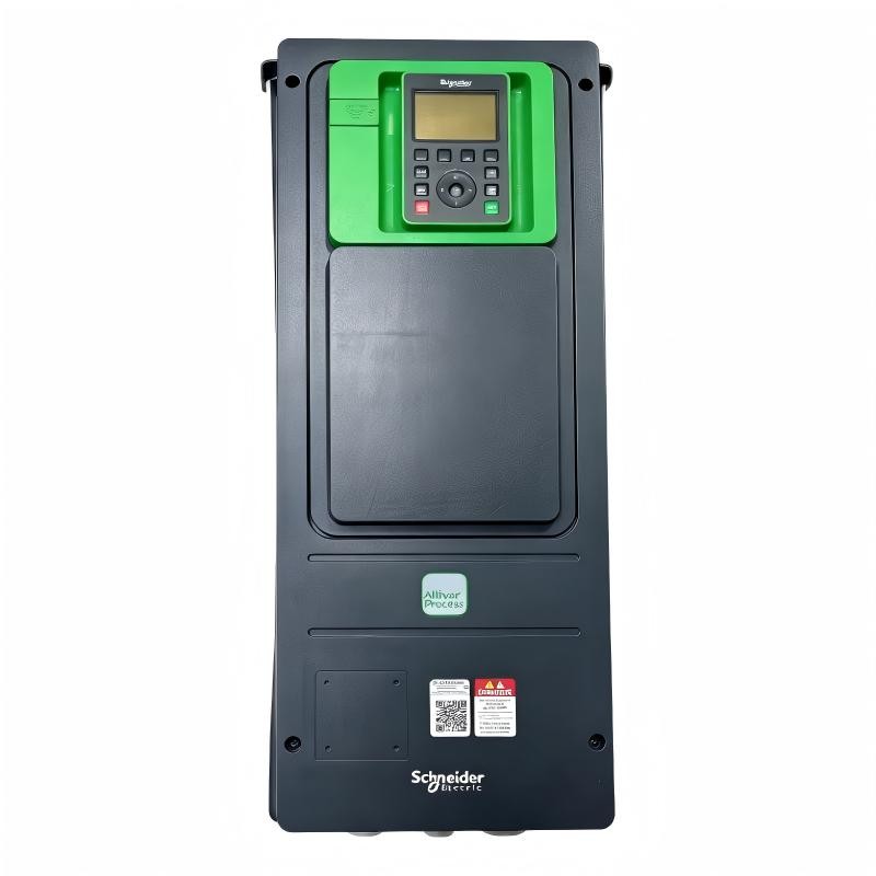
Pre-Installation Checks for the Schneider ATV650D22N4 Drive
Before mounting the drive, compare the equipment nameplate with the site's electrical design. The 22 kW rating applies to normal-duty operation; heavy-duty applications may require a different motor-power and current assessment. Confirm that the selected drive is appropriate for the motor's rated current and expected overload requirements.
The installation team should also verify the following:
The three-phase supply is compatible with the drive's rated voltage and frequency.
The enclosure location provides the clearances required by the installation manual.
Incoming protection and cable cross-sections comply with applicable electrical standards.
The motor protective earth and drive grounding connections are correctly arranged.
The PLC, operator panel, and network architecture are documented before control wiring begins.
The official Schneider Electric ATV630/ATV650 installation manual, document EAV64301, should be used to confirm the mounting dimensions, terminal specifications, and wiring requirements for the exact product version.
Schneider ATV650D22N4 Power Wiring and Control Interface Setup
Connect the incoming three-phase supply to L1, L2, and L3, and connect the motor leads to U, V, and W in accordance with the manufacturer's wiring diagram. Protective earth connections must be completed before energization.
Control wiring should be planned separately from the main motor circuit. Analog speed references, digital start commands, and communication cables can be affected by electromagnetic interference from motor leads. Use the specified cable types, shielding arrangements, and routing distances to reduce signal instability.
For PLC integration, document the command source, reference channel, communication protocol, and required interlocks. Confirm that the drive's System Configuration matches the PLC program. A valid network connection alone does not guarantee that start commands or speed references are mapped correctly.
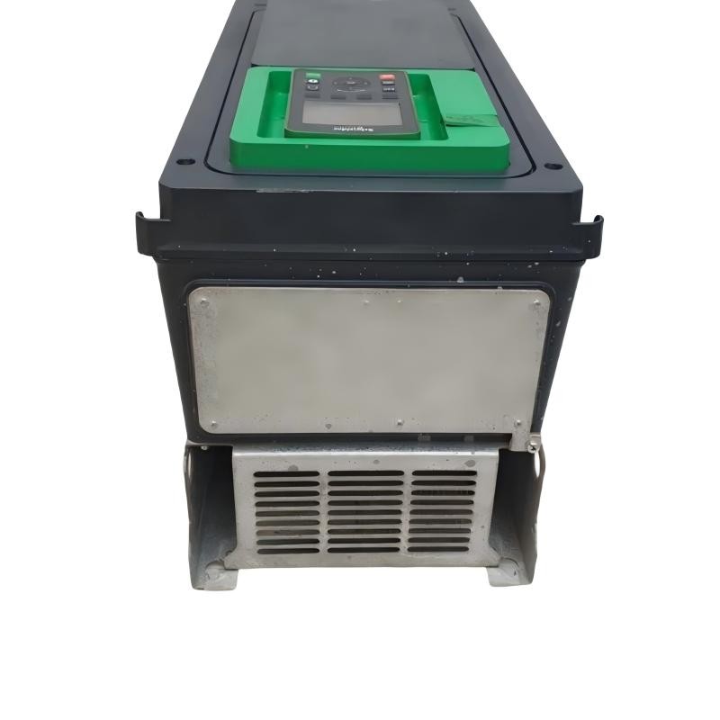
Schneider ATV650D22N4 Setup and Commissioning Procedure
Commissioning should progress from electrical verification to controlled motor operation. Begin with the motor nameplate data, including rated voltage, current, frequency, speed, and power factor where required by the selected control mode.
After checking the configuration, perform a controlled startup:
Inspect all power, grounding, and control connections with the equipment isolated.
Energize the drive according to the approved commissioning procedure and check for active faults.
Enter the motor parameters and confirm the selected control and reference channels.
Verify that emergency-stop and other required safety circuits operate independently as designed.
Test start, stop, and speed-reference commands at a low, permitted operating speed.
Check motor rotation, output current, acceleration, and mechanical response.
Increase the operating point gradually and record representative measurements.
For example, if a motor's nameplate current is 42 A, that value can serve as a reference when evaluating measured current under a defined load. It is only an illustrative example; the actual motor nameplate and application conditions must determine the acceptance criteria.
Validating Schneider ATV650D22N4 System Configuration
A completed Setup / Commissioning process should leave the drive with a documented and reproducible configuration. Confirm that PLC commands, speed feedback, fault reporting, and stop behavior agree with the approved control philosophy.
Record the final parameter settings, measured supply conditions, representative motor current, and any adjustments made during testing. Back up the drive configuration where supported and retain the electrical drawings alongside the commissioning record.
This baseline makes future Troubleshooting more efficient because engineers can compare abnormal behavior with known operating conditions instead of immediately assuming a failed power module.