Schneider ATV650D22N4 Variable Speed Drive Motor Overload Troubleshooting Guide
Time:2026-10-27 Browse: 3
Identifying Schneider ATV650D22N4 Motor Overload Faults
A Schneider ATV650D22N4 motor overload fault may result from excessive mechanical load, incorrect motor parameters, prolonged high current, or a mismatch between the selected duty rating and the actual application. The most useful Fault Diagnosis approach is to determine whether the abnormal current originates from the driven machine, motor, or drive configuration.
An overload that appears only during startup suggests a different investigation from one that develops after several hours of operation. Engineers should record the fault code, motor current, operating frequency, load condition, and time to trip before changing parameters.
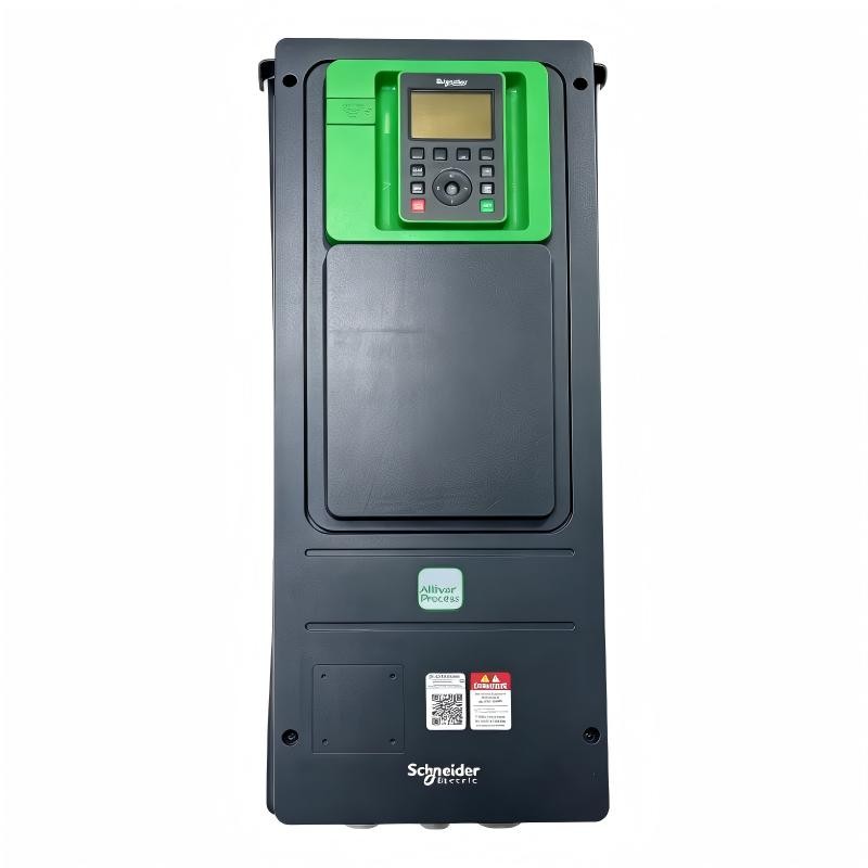
A Field-Based Diagnostic Approach to ATV650D22N4 Overload Trips
Consider a representative industrial troubleshooting scenario: a pump operates normally at reduced demand but trips when the process requires greater flow. The initial assumption may be that the variable speed drive is undersized, but this conclusion should not be made from the trip alone.
The engineer first compares the motor's rated current with the drive's configured motor current. Next, the investigation examines whether the current increases in proportion to process demand or rises unexpectedly at a particular operating point.
Suppose the motor nameplate specifies 40 A and the recorded current reaches 46 A during sustained operation. These are illustrative values, not measurements from a verified customer case. The difference would justify checking the load, motor parameters, and operating duty, but it would not by itself establish the root cause.
The diagnostic reasoning is straightforward:
If current increases with process demand, inspect the driven equipment and operating conditions.
If the configured motor current differs from the nameplate, correct the parameters using the approved procedure.
If current is high even at a low mechanical load, investigate motor wiring, phase conditions, and possible motor damage.
If the problem occurs after prolonged operation, review thermal conditions, ventilation, switching frequency, and load history.
Schneider ATV650D22N4 Motor Parameters and Current Analysis
The ATV650D22N4 is rated at 46.3 A nominal output current for the specified normal-duty rating at the manufacturer's stated conditions. This figure should not be treated as a universal motor-current limit: the motor's own rating, the drive duty selection, ambient conditions, and installation requirements all affect the permissible operating point.
Review the motor parameters stored in the drive and compare them with the motor nameplate. Confirm that the selected motor-control mode and thermal protection settings are suitable for the application.
Where current readings are available, compare measurements taken at similar speeds and process loads. A current increase accompanied by rising mechanical demand may indicate a process problem, whereas a sudden change without a corresponding load change warrants closer inspection of the electrical circuit and motor.
Before conducting electrical tests, isolate the equipment and follow the prescribed safety procedures. Insulation testing must be performed with the drive disconnected as required by the manufacturer's instructions; applying an insulation tester directly to connected drive electronics can damage the equipment.
Corrective Actions for Schneider ATV650D22N4 Overload Problems
The corrective action should match the confirmed cause rather than simply increasing the overload threshold.
For a mechanically overloaded pump, inspect the hydraulic operating point, impeller condition, valves, and process restrictions as appropriate. For incorrect motor data, correct the rated parameters and repeat the same controlled operating test. If the application exceeds the selected drive duty, have the engineering team verify whether the drive and motor are appropriately sized.
Where overheating is suspected, inspect ventilation paths, cooling-fan operation, cabinet conditions, and switching-frequency settings. Operation above the manufacturer's rated switching frequency may require output-current derating.
Do not repeatedly reset the drive or disable protective functions to maintain production. If the overload persists after the mechanical load, motor parameters, and supply conditions have been verified, a qualified technician should continue the investigation using the recorded fault history and appropriate service procedures.
Preventing Recurring Schneider ATV650D22N4 Faults
After the repair, repeat the operating condition that originally caused the trip. Record the current at relevant operating points, confirm stable operation across the required speed range, and check that the PLC Controller receives the expected fault and status signals.
Retain the fault history, parameter backup, and final test results. Comparing these records during later Fault Diagnosis can reveal gradual load changes, deteriorating motor conditions, or configuration drift before they cause repeated downtime.
For industrial maintenance teams, consistent measurements and evidence-based troubleshooting provide a more reliable path to restoring operation than replacing the drive without first establishing the cause.