Allen-Bradley 1203-FM1 FLEX I/O SCANport Module Overview
Time:2026-05-29 Browse: 26
The 1203-FM1 SCANport module acts as a communication bridge between SCANport devices (drives/controllers) and a Flex I/O backplane system. It is mounted on a dedicated 1203 terminal base (commonly 1203-FB1) and powered via the Flexbus system (5V DC logic supply).
In one retrofit project for a conveyor drive system, engineers initially assumed the module was defective because the SCANport devices were not responding. The actual issue was an incorrectly seated terminal base preventing Flexbus continuity.
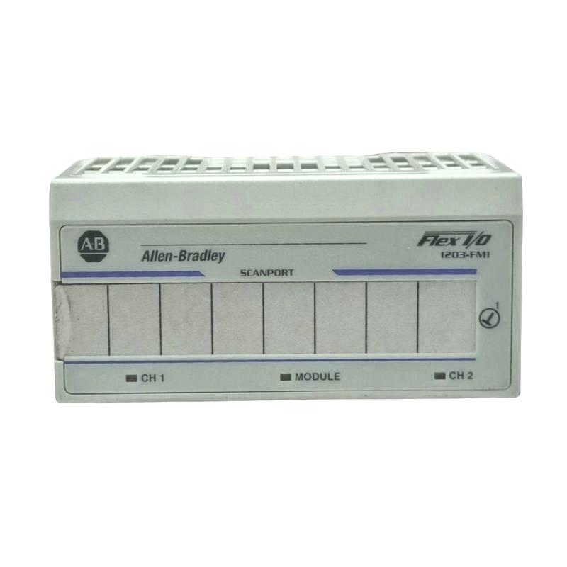
Allen-Bradley 1203-FM1 Pre-Installation Requirements
Before installation, verify:
Correct terminal base: only 1203-series base allowed
Stable Flexbus 5V supply from adapter
SCANport device compatibility (typically 1305 / 1336 series drives)
Proper grounding of cabinet backplane system
DIP/physical configuration recorded (if used in legacy systems)
Field experience shows that mixing terminal bases from other Flex I/O families will result in silent module failure (no comm, no fault LED).
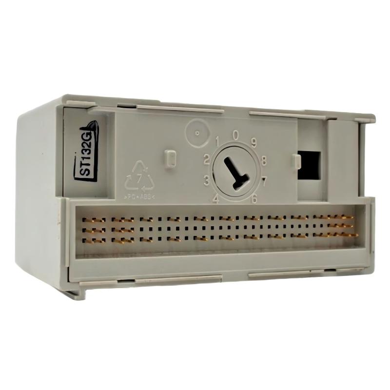
Allen-Bradley 1203-FM1 Mounting & System Setup
The installation sequence is sensitive due to Flexbus alignment:
Ensure Flexbus connector is fully engaged with adjacent module
Align module guide rails before insertion
Press module firmly until latch locks
Confirm channel LEDs initialize after power-up
In a commissioning case at a steel processing line, intermittent SCANport dropouts were traced to a half-seated module that passed visual inspection but failed under vibration load.
Allen-Bradley 1203-FM1 Commissioning & Validation
Once installed:
Verify Flexbus power (5V stable)
Check SCANport device recognition
Confirm LED status per channel (steady = healthy, flashing = comm issue)
Use DriveExplorer or legacy SCANport diagnostic tools if available
After full commissioning in a packaging system, SCANport response stabilized at consistent update cycles with zero comm retries over 24 hours.