Schneider ATV650D30N4 Variable Speed Drive Installation Guide for Motor Commissioning
Time:2026-10-27 Browse: 3
Schneider ATV650D30N4 Drive Installation Requirements
The Schneider ATV650D30N4 variable speed drive requires correct power wiring, motor parameter configuration, and control signal verification before commissioning. This 30 kW Altivar Process drive is designed for three-phase 380–480 V applications, and installation errors involving motor connections, grounding, or system configuration can prevent reliable operation even when the drive powers up normally.
For an effective Installation Guide, engineers should verify the incoming supply, motor nameplate, protective devices, and control architecture before applying power. The manufacturer's ATV630/ATV650 installation manual provides the applicable terminal and mounting requirements.
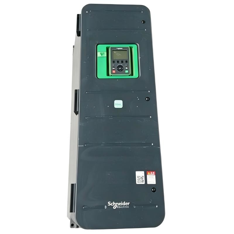
Preparing the Schneider ATV650D30N4 for Installation
Before mounting the PLC-controlled drive system, confirm that the cabinet provides sufficient clearance for ventilation and maintenance. Check the enclosure protection requirements, ambient temperature, cable entry arrangement, and grounding provisions.
The following information should be recorded during preparation:
Supply voltage and frequency, measured against the equipment rating.
Motor rated power, voltage, current, frequency, and speed.
Required speed range and load characteristics.
PLC Controller interface, including digital commands and analog speed references.
Network requirements for Modbus serial or Ethernet-based communication, where applicable.
The ATV650D30N4 belongs to the 30 kW frame-size B product group. Cable selection and protective-device ratings must follow the applicable installation documentation and the actual duty cycle rather than relying on power rating alone.
Schneider ATV650D30N4 Power Wiring and Grounding
The main power circuit connects the three-phase supply to L1, L2, and L3, while the motor connects to U, V, and W. Protective earth conductors must be connected according to the manufacturer's grounding instructions.
Incorrect phase connections, loose terminals, or inadequate cable sizing can cause excessive heating, unstable operation, or protective trips. For the D30N4 frame, the manufacturer's manual specifies a 12 N·m tightening torque for the listed output power terminals; verify the exact terminal and hardware arrangement before applying this value.
Control wiring deserves equal attention. Keep analog reference and communication cables separated from motor power cables. Use suitable shielded, twisted-pair wiring for control signals and terminate shields according to the installation design and EMC requirements.
Never connect the supply directly to the motor output terminals. Before working on the drive, isolate all energy sources, apply lockout/tagout procedures, and verify that the DC bus has discharged to a safe level using the prescribed method.
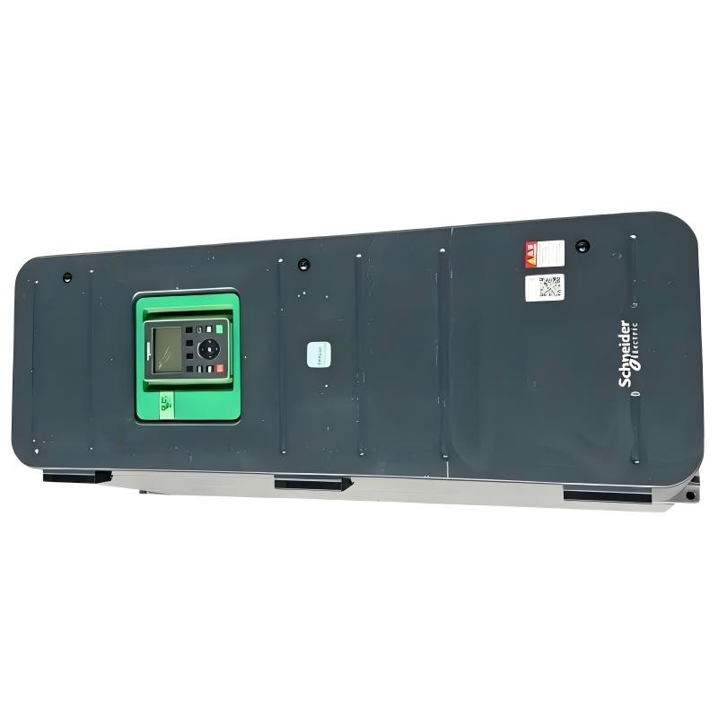
Schneider ATV650D30N4 Setup and Commissioning Strategy
Commissioning should begin with motor data rather than immediately running the machine at full speed. Enter the motor nameplate values and confirm the control mode, minimum and maximum frequency, acceleration and deceleration times, and command source.
A practical commissioning sequence is:
Inspect power and control wiring against the approved drawings.
Confirm that the drive's supply voltage is within its specified operating range.
Enter the motor's rated parameters and required operating limits.
Verify the selected command source and speed-reference source.
Test the start, stop, and speed-reference signals under controlled conditions.
Run the motor at a low, permitted speed and check rotation direction, current, and mechanical response.
Increase the speed gradually while monitoring current and process feedback.
For PLC integration, verify that the controller's command logic matches the drive's System Configuration. If the PLC sends a start command but the drive does not run, check the selected control channel, digital input assignments, interlocks, and any active safety function before changing motor parameters.
Schneider ATV650D30N4 Commissioning Validation
Successful commissioning requires more than the absence of a fault code. Record the supply voltage, motor current at representative operating points, acceleration behavior, communication status, and process response.
For example, during a controlled commissioning test, an engineer might record a motor current of 18 A at a particular operating point and compare it with the expected current for that load. This is an illustrative measurement, not a verified result for a specific installation. Actual acceptance limits must be established from the motor nameplate, load requirements, and engineering design.
A complete handover should include the final parameter backup, approved wiring drawings, PLC interface settings, and a record of any commissioning adjustments. These records simplify later Troubleshooting and provide a reliable baseline for Fault Diagnosis.