Allen Bradley 20BD011A0AYNANC0 PowerFlex 700 AC Drive Fault Diagnosis and Troubleshooting
Time:2026-10-26 Browse: 2
Diagnosing PowerFlex 700 Drive Trips During Motor Acceleration
Allen Bradley 20BD011A0AYNANC0 PowerFlex 700 AC Drive overcurrent or overvoltage trips during acceleration should be investigated through fault history, load conditions, motor wiring, and acceleration settings before the drive is classified as defective. The displayed fault code is the starting point for Fault Diagnosis; the operating conditions immediately before the trip usually provide the next important clue.
A drive that runs normally at steady speed but trips during startup presents a different diagnostic problem from one that trips immediately when power is applied. Separating these conditions helps prevent unnecessary replacement of the drive or motor.
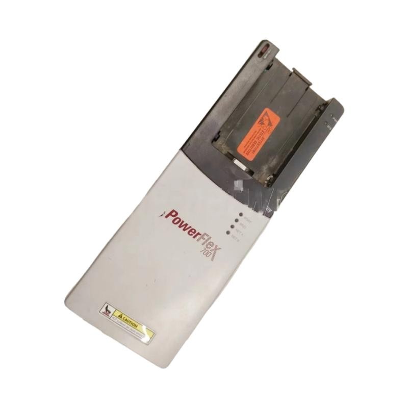
PowerFlex 700 Fault Symptoms and Diagnostic Evidence
Begin by recording the exact fault message or code from the drive interface. Preserve the fault history before resetting the drive, and note whether the event occurs at power-up, when a run command is issued, during acceleration, or under a sudden load change.
Useful observations include:
Whether the motor moves before the trip occurs.
Whether the trip is repeatable at the same speed or load.
Whether the fault appears only when the machine is mechanically loaded.
Whether supply voltage or DC bus readings change abnormally.
Whether the motor cable, grounding, or insulation has recently been disturbed.
For an overcurrent-type fault, inspect for mechanical binding, incorrect motor data, shorted output conductors, and acceleration settings that demand excessive torque. For an overvoltage fault during deceleration, investigate regenerative energy and the programmed stopping profile rather than assuming that the incoming supply is necessarily faulty.
A PowerFlex 700 Acceleration Fault: Field Diagnostic Approach
Consider a representative field scenario in which a conveyor drive runs successfully without a load but trips during loaded startup. The first observation is that the fault is linked to load, not simply to the application of power.
The technician should then compare motor nameplate current with the drive's configured motor data, inspect the conveyor for mechanical resistance, and review the acceleration ramp. If the motor current rises sharply just before the trip, the next check is whether the mechanical load or control settings explain the increase.
For illustration, suppose the motor current rises from 4 A during unloaded operation to 11 A under load. These are hypothetical readings, not measured results for this catalog number. Their significance depends on the actual motor rating, drive rating, measurement method, and fault code. A current increase alone does not establish a failed power transistor or motor winding.
Only after mechanical loading, parameter configuration, wiring, and supply conditions have been evaluated should internal drive hardware become a leading suspect.
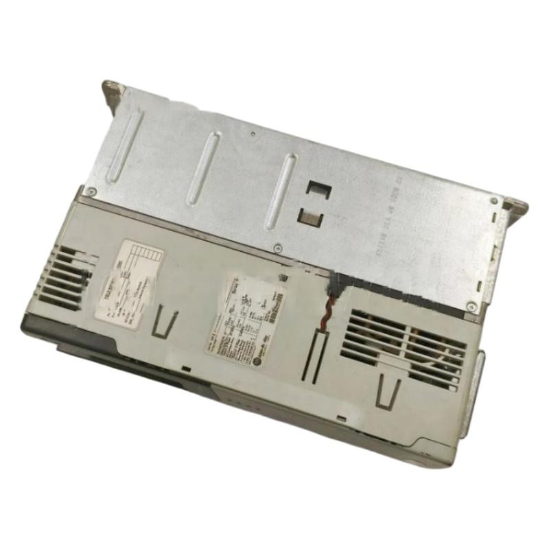
Corrective Actions for 20BD011A0AYNANC0 Overcurrent or Overvoltage Trips
Correct the identified cause rather than repeatedly resetting the drive. If motor parameters do not match the nameplate, enter the correct values and repeat a controlled test. If the load is binding, correct the mechanical problem before commissioning again. If the acceleration or deceleration profile is unsuitable, adjust it within the machine's operating limits and the manufacturer's guidance.
For suspected cable or motor insulation problems, isolate all power sources and follow approved insulation-testing procedures. Disconnect the drive electronics as required by the manufacturer's instructions before applying an insulation tester; applying test voltage through connected drive electronics can damage components.
If a trip persists with verified motor data, acceptable mechanical loading, and sound wiring, record the fault code and operating conditions for qualified drive service personnel. Do not replace internal components based solely on a generic overcurrent or overvoltage indication.
PowerFlex 700 DC Bus and Supply Checks During Fault Diagnosis
A DC bus-related fault requires a different line of investigation from a motor overload. Check the recorded fault timing, incoming supply condition, stopping behavior, and the drive's documented DC bus measurement procedure.
An overvoltage event that occurs only during rapid deceleration may indicate that the motor is returning energy to the drive faster than the system can manage it. Depending on the application and drive configuration, the solution may involve a suitable deceleration profile or a manufacturer-approved braking arrangement.
Conversely, an undervoltage event may require inspection of the incoming supply, fuses, contactors, and supply stability. Measurements must be compared with the exact model's specifications; a universal voltage threshold should not be assumed.
Before opening the enclosure, isolate the equipment, observe the specified DC bus discharge time, and verify absence of hazardous voltage with an appropriate instrument. A displayed stopped status does not prove that the DC bus is safe.
Troubleshooting the PLC Controller and PowerFlex 700 Command Path
If the drive reports no internal fault but fails to start, investigate the command path rather than concentrating exclusively on the power stage. Verify the selected start-command source, PLC output state, terminal input configuration, permissive conditions, and communication status.
A useful diagnostic sequence is to compare three states: the command requested by the PLC, the command received by the drive, and the drive's actual running status. If these states disagree, inspect the relevant wiring, network mapping, and System Configuration.
For a network-controlled drive, check the communication adapter's status and the validity of the command and feedback data. For hardwired control, verify the actual terminal state and control reference using the documented procedure. Do not bypass machine safety circuits to force a test run.
Repair Verification and Return-to-Service Criteria
After a corrective action, clear the fault according to the approved procedure and repeat the operating condition that originally caused the trip. Confirm that the drive starts, accelerates, runs under representative load, and stops correctly without recurring faults.
A repair record should include the original fault code, operating conditions, measurements, corrective work, and post-repair observations. If a power module, gate-drive circuit, or other internal assembly is suspected, use qualified service personnel and the manufacturer's repair guidance rather than attempting an unsupported component-level repair.
Successful Fault Diagnosis means identifying a supported root cause and verifying the result under controlled operating conditions—not simply resetting the fault and observing that the motor runs once.
Long-Tail Keywords for Allen Bradley 20BD011A0AYNANC0 Troubleshooting
This troubleshooting guide covers Allen Bradley 20BD011A0AYNANC0 PowerFlex 700 fault diagnosis, PowerFlex 700 overcurrent during acceleration, PowerFlex 700 DC bus overvoltage troubleshooting, Allen Bradley AC drive not starting, PowerFlex 700 PLC communication checks, and variable frequency drive repair verification. Use the exact fault code, catalog-number documentation, and recorded operating data to distinguish configuration problems from wiring, motor, supply, or internal drive failures.