Woodward 9907-175A Load-Sharing Module Installation and Commissioning Guide
Time:2026-10-22 Browse: 2
Woodward 9907-175A Load-Sharing Module Installation Overview
The Woodward 9907-175A Load-Sharing Module should be installed with careful attention to control-system compatibility, signal wiring, grounding, and generator governor integration. Incorrect wiring or incompatible configuration can prevent the load-sharing system from coordinating generator output correctly, even when each generator operates normally on its own.
Before beginning installation, verify the exact 9907-175A part number and obtain the applicable Woodward technical documentation. The module's terminal assignments, supply requirements, signal characteristics, and adjustment procedures must be confirmed from the documentation for the specific hardware revision rather than inferred from another load-sharing module.
How the Woodward 9907-175A Module Fits into Generator Control
In a parallel-generator installation, load-sharing equipment helps coordinate the contribution of individual generator sets to a common electrical load. The load-sharing control system works with the associated generator controllers and governors to regulate real-power distribution according to the configured operating strategy.
Successful synchronization does not necessarily indicate successful load sharing. Two generators may connect to the same bus while carrying different proportions of the load because of signal, configuration, calibration, or governor-response problems.
The 9907-175A installation should therefore be evaluated as part of the complete generator control architecture, including the connected controllers, interconnecting signals, and the equipment responsible for adjusting engine power.
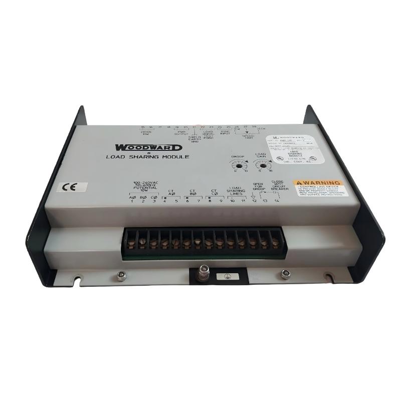
Woodward 9907-175A Installation Preparation and System Configuration
Before mounting the module, establish the installation requirements and document the existing control-system arrangement.
Hardware verification: Confirm the model designation, revision information, connector condition, and compatibility with the intended application.
Electrical requirements: Verify the specified supply voltage, terminal functions, signal ranges, and grounding requirements against the manufacturer documentation.
Control architecture: Identify the participating generator controllers, governor interfaces, and load-sharing connections.
Panel installation: Check mounting security, enclosure conditions, cable routing, and protection against vibration and contamination.
Baseline records: Document existing wiring and relevant controller settings before making changes.
Apply the site's isolation and lockout procedures before handling wiring. Where commissioning involves live generator equipment, follow the approved electrical safety procedures and operating limits.
Woodward 9907-175A Module Wiring and Signal Integrity
Correct wiring is fundamental to a reliable Installation Guide and commissioning process. Use the approved terminal diagram to identify every connection; do not rely on terminal positions or wire colors from another model.
Inspect signal conductors for damaged insulation, loose terminals, corrosion, and intermittent connections. Check shielding and grounding arrangements against the system design, particularly where low-level control signals run near power conductors.
For a system involving multiple generators, inspect the complete load-sharing signal path rather than concentrating only on the 9907-175A. A disconnected conductor or incorrect connection at another controller can produce symptoms that appear to originate from the module under investigation.
Do not energize the module or inject test signals until the required electrical ratings and measurement points have been verified.
Woodward 9907-175A Setup and Commissioning Strategy
Commissioning should progress from static inspection to functional validation.
Electrical inspection: Verify the physical installation and compare the wiring with the approved diagram. Measure supply and reference conditions at the documented test points using suitable instruments.
Configuration review: Confirm that the connected controllers use compatible load-sharing arrangements and that the intended operating mode is correctly configured.
Pre-start checks: Complete the required control-system checks before starting or connecting generator sets. Confirm that protective functions and interlocks remain operational.
Functional testing: Under the approved commissioning procedure, observe the load-sharing response as generators enter parallel operation and the electrical demand changes.
Acceptance documentation: Record the operating conditions, measured signals, controller settings, and test results. Use manufacturer-defined limits and site-specific acceptance criteria rather than assumed universal values.
Woodward 9907-175A Load-Sharing Commissioning: Practical Engineering Example
Consider a representative commissioning scenario in which two generators synchronize successfully, but one generator carries a larger proportion of the real-power load than expected.
The first task is to verify the actual power readings. If independent measurements confirm the imbalance, the engineer should examine the load-sharing signal path, controller configuration, and governor response before deciding that the module is defective.
For example, readings of 300 kW and 200 kW would represent unequal output if the operating strategy calls for equal real-power sharing and the units have comparable ratings. These figures are illustrative diagnostic values, not published specifications or documented test results for the 9907-175A.
The next decision depends on the evidence. An incorrect or unstable control signal points toward wiring or interface checks. A stable signal accompanied by an inconsistent engine-power response directs attention toward controller settings, governor calibration, or the mechanical power response.
Woodward 9907-175A Installation Guide: Final Verification
A successful Setup / Commissioning process requires more than confirming that the module is powered and connected. The complete control system must demonstrate the required behavior under the specified operating conditions.
Before handover, confirm that the wiring has been checked, configuration records are complete, relevant functional tests have passed, and outstanding issues have been documented. Retain the baseline measurements so maintenance personnel can compare future operating behavior with the original commissioning condition.
This evidence-based approach makes later Troubleshooting and Fault Diagnosis more efficient and reduces the risk of misidentifying an external control-system issue as a module failure.