Allen-Bradley MPL-B880C-SJ72AA Servo Motor Installation Guide (Mounting & Setup)
Time:2026-10-20 Browse: 1
Allen-Bradley MPL-B880C-SJ72AA Servo Motor Installation Overview
The Allen-Bradley MPL-B880C-SJ72AA servo motor requires correct mechanical alignment, compatible drive configuration, and verified feedback connections to achieve reliable motion control. This MP-Series low-inertia brushless AC servo motor is designed for 460 V-class applications, with a 265 mm frame size, 203.2 mm magnet stack length, and a rated speed of 1500 rpm. It uses a high-resolution single-turn encoder, a keyed shaft, and a right-angle SpeedTEC DIN connector; this specific version does not include a holding brake. <Cite refs={["turn278477search0","turn278477search1"]}/>
During installation, the main engineering objective is to establish a reliable connection between the mechanical load, motor power circuit, feedback system, and servo drive. A motor that is mechanically secure but incorrectly configured in the motion controller may produce position errors, excessive following error, or an unsuccessful startup.
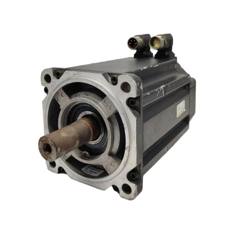
Mechanical Preparation for the MPL-B880C-SJ72AA Servo Motor
Before mounting the motor, compare the nameplate with the machine design and verify the shaft dimensions, mounting interface, coupling arrangement, and required torque. Inspect the housing, shaft, connectors, and mounting pilot for transport damage.
The 265 mm frame and 203.2 mm magnet stack determine important aspects of the installation envelope. Confirm that the machine provides adequate clearance for the motor body, cable connectors, and maintenance access.
When coupling the motor to a gearbox, ball screw, or other driven mechanism, align the shafts within the coupling manufacturer's tolerances. Do not use the motor shaft to pull misaligned components together. Excessive radial or axial loading can damage bearings and shorten service life.
The motor has no holding brake. If the application requires the load to remain stationary after drive power is removed, provide a suitable external mechanical holding arrangement and assess the risks of gravity-driven or back-driven movement.
Electrical Connection and Encoder Feedback Setup
The MPL-B880C-SJ72AA uses a 460 V-class power configuration and a single-turn high-resolution feedback encoder. Select the compatible servo drive and motor power and feedback cables using the manufacturer's selection documentation. Verify the actual drive model and the motor's nameplate before making electrical connections.
Keep motor power conductors separated from sensitive feedback wiring in accordance with the installation requirements. Inspect connector pins, cable routing, strain relief, and grounding arrangements. Ensure that the right-angle SpeedTEC connector is securely installed without placing excessive mechanical stress on the cable.
Do not infer the connector pinout from another MPL motor model. Confirm the correct terminal assignments and cable compatibility in the applicable Rockwell Automation documentation.
Before connecting or disconnecting motor cables, isolate the equipment and follow the drive manufacturer's discharge-time and electrical safety requirements. Never handle power or feedback connectors while the system is energized.
Allen-Bradley MPL-B880C-SJ72AA Servo Drive Configuration
Successful Setup depends on selecting the correct motor identity and feedback parameters in the motion-control system. In the engineering software, verify the motor catalog entry, feedback type, rated speed, drive voltage class, and applicable current and thermal protection settings.
The 1500 rpm rating should be reflected in the application limits where appropriate. However, rated speed alone does not determine the correct acceleration, deceleration, torque limit, or position-loop tuning. These values depend on the load inertia, coupling stiffness, machine mechanics, and process requirements.
During initial commissioning, keep motion limits conservative and ensure that the machine can move safely through the intended test range. Verify the direction of rotation and feedback polarity using the approved commissioning procedure before enabling automatic motion.
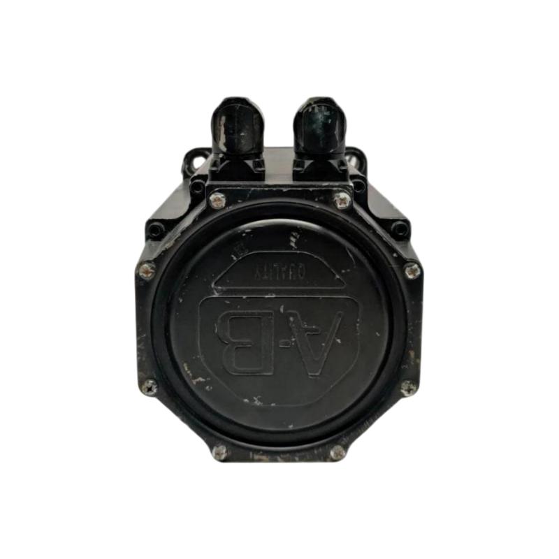
Commissioning Checks for the MPL-B880C-SJ72AA Motor
A controlled commissioning sequence should establish whether the motor, drive, feedback, and mechanical load behave as one system.
First, verify that the drive recognizes the configured motor and reports no unresolved startup faults. Next, perform the manufacturer's recommended feedback and motor identification checks. Where permitted, test movement at low speed and with a limited travel range.
Observe actual position, commanded position, motor speed, current, and following error during the test. Unexpected current spikes or rapidly increasing following error can indicate mechanical binding, incorrect feedback configuration, or an unsuitable motion profile.
For example, if the motor moves in the opposite direction to the command during a low-speed test, stop the commissioning sequence and investigate the motion configuration and wiring against the manufacturer's instructions. Do not compensate for an unresolved feedback or direction problem by simply increasing the torque limit.
Allen-Bradley MPL-B880C-SJ72AA Installation Validation
After initial motion is verified, test the axis at several operating points within the approved machine limits. Confirm repeatable positioning, smooth acceleration, stable feedback, and acceptable motor temperature.
In a representative commissioning scenario, an axis may complete its first low-speed movement successfully but develop a following error when acceleration increases. The appropriate engineering response is to compare the motion profile with the load inertia, inspect the mechanical coupling, and review the drive's current and following-error data before changing the tuning parameters.
This is an illustrative diagnostic scenario rather than a documented field event involving a specific motor.
Record the final drive configuration, motor identity, feedback status, motion limits, and test results. The installation is ready for production only after the complete axis passes the required safety and performance checks.
Long-Tail Installation Guide for the Allen-Bradley MPL-B880C-SJ72AA
For engineers searching for Allen-Bradley MPL-B880C-SJ72AA servo motor installation, encoder setup, mounting alignment, and commissioning guidance, the key is to validate mechanical and electrical compatibility together.
The motor's 460 V-class configuration, 1500 rpm rated speed, single-turn encoder, keyed shaft, and no-brake design must all be reflected in the actual application. Confirm the exact catalog number and use the applicable manufacturer documentation before applying power or enabling motion.