Allen Bradley 1606-XL240E Power Supply Installation Guide
Time:2026-07-15 Browse: 16
Allen Bradley 1606-XL240E Power Supply Installation Overview
The Allen Bradley 1606-XL240E Power Supply Installation Guide explains the practical installation, wiring, and commissioning methods for integrating this 24V DC power supply into industrial automation systems. The 1606-XL240E is commonly installed in control panels to provide stable DC power for PLC Controller systems, I/O modules, sensors, relays, and industrial communication devices.
In field applications, many startup problems are not caused by PLC hardware failure but by unstable DC power conditions. Incorrect wire sizing, poor grounding, or improper load distribution can affect the complete System Configuration and create intermittent machine faults.
The purpose of this Installation Guide is to help engineers establish a reliable power foundation before PLC programming, I/O testing, and machine commissioning.
Allen Bradley 1606-XL240E Power Supply Installation Preparation
Before mounting the Allen Bradley 1606-XL240E, engineers should evaluate the complete electrical environment instead of treating the Power Supply as an independent component.
Important preparation checks include:
Confirm AC input availability and stability
Calculate total 24V DC load requirements
Check cabinet temperature and ventilation conditions
Review PLC Controller and field device power consumption
Plan separation between power cables and signal cables
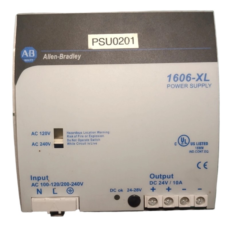
The 1606-XL240E provides a 24V DC output system with a rated output power of 240W and approximately 10A output capability. This capacity allows it to supply multiple automation devices when the load is correctly calculated.
During one machine upgrade project, a 1606-XL240E was added to replace an older DC power unit. The engineering team initially calculated only the PLC and remote I/O load but missed several additional devices, including proximity sensors and pneumatic control valves.
The measured operating current reached 8.7A during normal production, leaving limited capacity for future expansion. After redesigning the DC distribution and adding a separate branch circuit for high-current devices, the system achieved stable operation.
Allen Bradley 1606-XL240E Power Supply Mounting and Wiring Method
The physical installation quality directly affects long-term reliability.
The recommended installation practices include:
Install the unit firmly on the DIN rail
Maintain sufficient airflow around the power supply
Connect protective earth before applying power
Use suitable wire sizes according to load current
Tighten terminal connections according to electrical standards
The basic wiring arrangement includes:
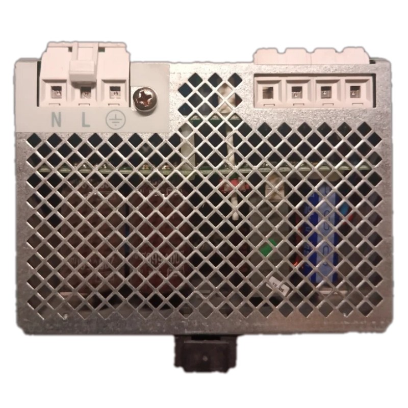
AC Input Connection
Line terminal
Neutral terminal
Protective earth terminal
DC Output Connection
Positive 24V DC distribution
0V DC common reference
For PLC Controller applications, the 0V reference is especially important. Poor DC reference connections can create communication errors, unstable analog signals, and unexpected Module behavior.
Allen Bradley 1606-XL240E Setup and Commissioning Procedure
The Setup and Commissioning stage should verify the actual operating condition of the complete control system.
Recommended checks include:
Confirm correct output polarity
Measure DC output voltage before connecting loads
Check voltage stability after PLC startup
Test operation during motor and actuator switching
Verify communication stability between PLC and field devices
A commissioning engineer should not only check whether the Power Supply LED is active. A power supply may appear normal without load but fail when multiple devices start simultaneously.
In one commissioning case, a 1606-XL240E installation passed the initial power-on test. However, the PLC Controller restarted whenever a conveyor motor contactor was energized.
Field measurements showed:
Idle output voltage: 24.4V DC
Voltage during contactor activation: 22.1V DC
Further investigation found excessive voltage drop caused by long undersized DC cables. After replacing the wiring and improving the distribution layout, the voltage remained above 24V DC during switching events.
Allen Bradley 1606-XL240E System Configuration Validation
After electrical commissioning, the complete System Configuration should be tested under real production conditions.
Validation points include:
PLC Controller remains in RUN status
Remote I/O modules maintain communication
Sensors provide stable signals
Relays and actuators operate correctly
No DC undervoltage alarms appear
A practical field test is operating the machine through different load conditions:
Idle operation
Maximum actuator activity
Motor startup sequence
Emergency stop recovery
During one factory acceptance test, a 1606-XL240E successfully powered the PLC system, but several analog Module readings fluctuated.
The power measurement showed stable 24V DC output. The actual issue was incorrect grounding between the sensor shield and control cabinet earth point.
After correcting the grounding method, the sensor signal returned to normal without replacing any hardware.
Allen Bradley 1606-XL240E Power Supply Installation Recommendations
Reliable installation depends on both electrical design and field experience.
Recommended practices:
Avoid connecting large inductive loads directly with sensitive control devices
Keep DC wiring organized and labeled
Check terminal tightness during maintenance
Monitor DC voltage during machine startup
Leave enough capacity for future system expansion
A properly installed Allen Bradley 1606-XL240E Power Supply provides a stable foundation for PLC Controller, Module, and Sensor applications in industrial automation systems.