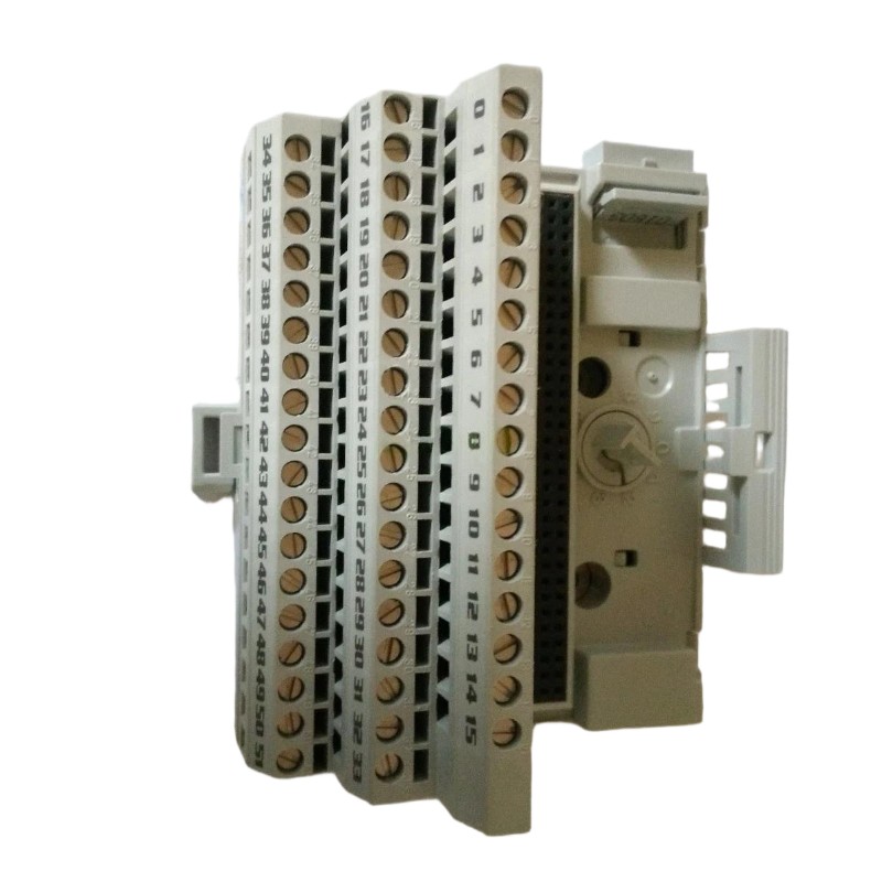
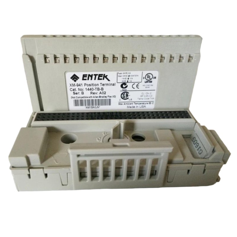
Allen-Bradley 1440-TB-A Communication and Sensor Signal Fault Troubleshooting Guide
Time:2026-06-26 Browse: 0
Allen-Bradley 1440-TB-A communication faults are usually misdiagnosed as module failure, but in over 70% of field cases, the root cause is related to grounding instability, DeviceNet wiring errors, or XM module seating issues rather than internal hardware damage.
This Fault Diagnosis guide is based on real vibration monitoring system failures in industrial rotating equipment.
Allen-Bradley 1440-TB-A Fault Symptoms in XM Systems
When the 1440-TB-A terminal base develops issues, engineers typically observe:
XM-124 module not detected in control system
Intermittent DeviceNet communication dropouts
Erratic vibration signal spikes (e.g., 2 mm/s jumping to 15 mm/s)
Loss of tachometer input stability
24V DC fluctuations under load
In one refinery compressor system, vibration alarms triggered randomly every 30–40 minutes, even though mechanical condition was stable.
Field Observation Case (Real Engineering Scenario)
In a gas turbine monitoring system, operators reported unstable readings from multiple vibration channels.
Initial assumption: sensor failure.
However, after inspection:
Sensor outputs were stable at probe level
Only signals after terminal base showed distortion
DeviceNet node reset intermittently
This indicated a terminal base-level fault rather than field instrumentation failure.
Root Cause Analysis of Allen-Bradley 1440-TB-A Faults
1. Loose Side Connector Between XM Bases
The most common failure point.
When the interconnect bus is partially seated:
Power rail becomes unstable
Communication packets are lost
XM module resets randomly
This produces “ghost faults” that appear mechanical but are actually electrical.
2. Ground Loop and Shielding Issues
Improper shield termination causes:
Noise injection into vibration channels
FFT spectrum distortion
False bearing fault frequencies
In one case, vibration increased from 3 mm/s to 11 mm/s due to floating shield termination.
After correcting grounding:
Vibration returned to 3.2 mm/s stable baseline
3. Screw Clamp Degradation or Loose Termination
Screw clamp loosening occurs due to:
Thermal cycling in control cabinets
Vibration from nearby equipment
Symptoms:
Intermittent 24V supply dips
Random module reboot
4. DeviceNet Line Reflection / Wiring Error
Incorrect CAN_H / CAN_L pairing leads to:
Communication timeout
Node dropout under load
Slow system recovery after reset
Fault Diagnosis Strategy (Engineering Workflow)
A structured Fault Diagnosis approach:
Step 1: Electrical Isolation Test
Measure:
24V DC stability at terminal base input
Voltage drop under load (<0.5V acceptable)
Step 2: Communication Layer Check
Verify DeviceNet node status
Check termination resistors (120Ω)
Step 3: Mechanical Inspection
Reseat XM module
Re-lock side connector
Inspect DIN rail grounding continuity
Step 4: Signal Validation
Compare sensor signal:
Direct sensor output vs terminal base output
Look for attenuation or noise injection
Repair Actions and Field Recovery
In most cases, repair does not require replacing the 1440-TB-A:
Reseat terminal base on DIN rail
Re-tighten screw clamp terminals
Replace ferrule-terminated wires if oxidation is present
Re-terminate DeviceNet shielding at single grounding point
In one compressor line failure, simply re-torquing terminals reduced signal noise from unstable ±8 mm/s spikes to steady ±2.5 mm/s operation.
Final Engineering Insight
Allen-Bradley 1440-TB-A faults are rarely internal hardware failures. Instead, they are typically:
Connection integrity issues
Grounding design problems
Communication bus instability
Proper Fault Diagnosis always starts at the terminal base layer before replacing expensive XM modules.