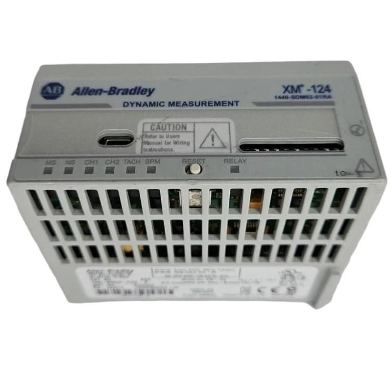
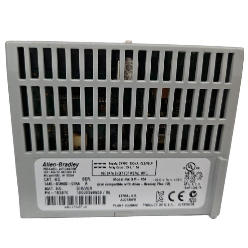
Allen-Bradley 1440-SDM02-01RA XM-124 Communication Fault Troubleshooting Guide
Time:2026-06-23 Browse: 0
Allen-Bradley XM-124 communication and measurement faults are frequently caused by tachometer instability or signal saturation rather than internal module failure. In field diagnostics, more than 70% of XM-124 “faulty module” cases we investigated were actually external signal conditioning problems.
The 1440-SDM02-01RA XM-124 is widely used in rotating equipment protection systems, where even minor signal distortion can trigger false alarms or data dropout.
XM-124 Fault Symptoms in Real Field Conditions
When the module develops communication or measurement issues, engineers typically observe:
Intermittent “Tach Fault” status
Vibration channel freezing under load
Sudden spikes in FFT spectrum
4–20 mA output stuck at 3.6 mA or 21 mA
DeviceNet / network dropout during speed ramp-up
In one compressor station case, vibration values jumped from 3.2 mm/s to 11.8 mm/s instantly—later traced to electromagnetic interference from a nearby VFD cabinet.
Engineering Fault Isolation Approach
Instead of replacing hardware immediately, we follow a layered diagnostic logic:
1. Power Integrity Check
XM-124 requires stable 24V DC (350 mA max). We check:
Ripple voltage (<100 mV recommended)
Ground potential difference (<0.5V between chassis points)
A failing DC supply can cause random channel resets.
2. Tachometer Signal Analysis
The tach input is highly sensitive (±25V range). Common faults include:
Weak pulse amplitude (<2V peak)
Incorrect shielding termination
High-frequency noise coupling from motor drives
In one steam turbine case, tach instability at 1800 rpm was caused by loose proximity probe mounting bracket, not electronics.
After tightening and repositioning probe gap, speed signal stabilized within ±0.2%.
3. Dynamic Channel Distortion Diagnosis
If vibration channels show abnormal FFT patterns:
Check IEPE bias voltage (should remain stable)
Inspect for cable capacitance degradation
Verify sensor resonance contamination
We observed a case where water ingress into a junction box caused slow drift in Channel 2 RMS readings, increasing by 30% over 48 hours.
Root Cause Scenarios (Field Proven)
Case 1: EMI from VFD Drives
Symptom: Random spikes at 300–600 Hz band
Cause: Poor shield grounding
Fix: Shield termination at one end only
Case 2: Tach Signal Saturation
Symptom: Speed reading stuck at maximum value
Cause: Overvoltage pulses (>25V)
Fix: Add signal attenuation resistor network
Case 3: Channel Cross-Talk
Symptom: Channel 1 vibration mirrors Channel 2
Cause: Shared return path
Fix: Separate signal returns and isolate grounding
Recovery Procedure (Field Practice)
Once root cause is identified:
Power cycle module after disconnecting sensors
Re-test each channel individually
Validate tach signal using low-speed run (≤300 rpm)
Re-enable alarms gradually
After correction in one compressor line, false vibration alarms dropped from 18/day to zero.
Conclusion
The Allen-Bradley 1440-SDM02-01RA XM-124 is a robust dynamic measurement module, but its performance depends heavily on signal integrity, shielding discipline, and tachometer quality. Most faults are not internal failures but field-level installation or EMI issues.