Allen-Bradley 1336F-MCB-SP1F Drive Control Board Installation Guide
Time:2026-06-17 Browse: 1
Allen-Bradley 1336F-MCB-SP1F control board installation issues are often misdiagnosed as drive failure, but in field commissioning most problems actually come from incorrect J2/J4 interface alignment, TB2 wiring errors, or improper grounding of the PLC communication loop rather than hardware damage.
In one commissioning case of a 1336 Plus II drive controlling a 55kW conveyor system, the drive repeatedly failed to enable after board replacement. The issue was traced not to the control board itself, but to a missing neutral reference on TB3 logic input, causing enable interlock logic to remain open.
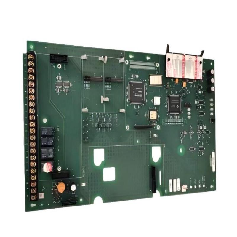
<h2>1336F-MCB-SP1F PLC Control Board Role in Allen-Bradley 1336 Drive System</h2>
The 1336F-MCB-SP1F acts as the main logic controller inside the Allen-Bradley 1336 Plus II PLC-based drive architecture. It coordinates:
Speed reference processing (analog / serial input)
Fault handling logic (overcurrent, undervoltage, enable faults)
Communication interface with HIM module
I/O routing via TB2 and TB3 terminal blocks
Unlike simple inverter boards, this module is tightly integrated with the velocity and current processor structure. Any misalignment in connectors (especially J1–J8 ribbon paths) can prevent system initialization during startup.
<h2>Preparation Strategy Before Installing 1336F-MCB-SP1F Control Board</h2>
Before replacing or installing the board, field engineers should verify:
DC bus voltage fully discharged (<5V recommended)
No residual charge in capacitor bank
Proper isolation of TB2/TB3 external control wiring
ESD grounding on chassis frame
In a real retrofit case, a technician replaced the board without discharging the DC bus. The result was immediate CPU latch failure and communication fault on HIM display, even though the board itself was not defective.
<h2>1336F-MCB-SP1F Wiring Configuration and Interface Alignment Issues</h2>
Most installation failures are caused by incorrect interface seating rather than wiring design errors.
Key areas to check:
J2/J4 board-to-board connectors fully seated
TB2 control terminal torque consistency
Shield grounding of analog speed reference cable
TB3 enable interlock loop continuity
A common field mistake is leaving TB3-30 enable loop open. In that condition, the drive displays an “Enable Fault” and refuses to start even if all parameters are correct.
<h2>1336 Plus II Drive Commissioning Behavior After Control Board Replacement</h2>
During commissioning, the system typically enters a reset phase:
HIM shows initialization screen (F01 reset state)
Current processor LED cycles green/red briefly
Parameter synchronization occurs between CP and VP modules
In one startup case, vibration in downstream motor initially reached 11.8 mm/s due to unstable torque reference. After correcting analog input scaling (0–10V mapped incorrectly to 0–60Hz), vibration dropped to 3.2 mm/s and torque stabilized.
<h2>Validation Logic for 1336F-MCB-SP1F Installation Success</h2>
Successful installation should be confirmed through:
Stable DC bus voltage during acceleration
No intermittent HIM communication loss
Motor current linear response to speed reference
No Enable / Auxiliary interlock faults
If the system passes 30-minute loaded runtime without fault buffer increment, installation can be considered stable.