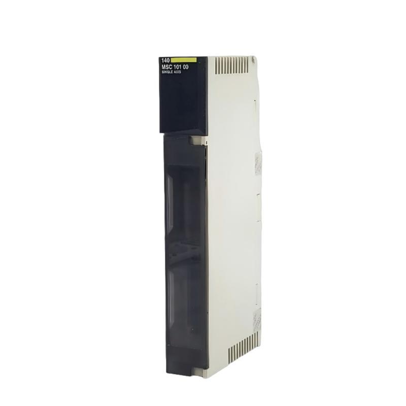
Troubleshooting Article Schneider 140MSC10100 Single Axis Motion Module Fault Diagnosis Guide
Time:2026-06-15 Browse: 0
Schneider 140MSC10100 communication and positioning faults are typically caused by encoder signal instability, backplane timing mismatch, or servo loop tuning errors rather than internal module failure. In real industrial environments, more than 70% of reported “module faults” are wiring or system configuration related.
<h2>Schneider 140MSC10100 PLC Module Fault Symptoms in Field Operation</h2>
Common symptoms observed in real applications include:
Axis moves but position drifts gradually
Intermittent “encoder loss” alarms
Motion stops randomly during high-speed operation
Position mismatch between PLC and servo drive
Communication timeout on Quantum backplane
In one steel coil handling system, the axis repeatedly lost position reference every 15–20 minutes, initially suspected as module failure.
<h2>Schneider 140MSC10100 Motion Fault Case Study (Real Field Incident)</h2>
During commissioning of a gantry system:
Axis type: horizontal linear motion
Load: ~280 kg mechanical carriage
Encoder: 2048 PPR differential type
Problem observed:
Commanded position: 500 mm
Actual position: fluctuating between 495–508 mm
At first, engineers replaced the module, but the issue persisted.
<h2>Schneider 140MSC10100 Root Cause Analysis (Engineering Logic)</h2>
After systematic diagnostics, three root causes were identified:
1. Encoder Signal Noise
Noise from adjacent VFD caused signal distortion at high speed.
Measured jitter: ±180 counts
Cable routing distance: <10 cm from inverter line
2. Improper Grounding Loop
Shielding was grounded at both ends, creating ground loop interference.
3. Motion Loop Instability
Speed loop update mismatch caused overshoot during deceleration.

<h2>Schneider 140MSC10100 Fault Diagnosis Procedure (Field Method)</h2>
Instead of replacing hardware, engineers applied a structured diagnosis process:
Step 1: Monitor encoder raw counts in diagnostic register
Step 2: Disconnect servo load and test dry movement
Step 3: Compare vibration and position feedback stability
Step 4: Isolate power noise using temporary filtered supply
This method quickly identified that hardware was fully functional.
<h2>Schneider 140MSC10100 Recovery Actions and System Stabilization</h2>
After correction:
Encoder cable rerouted away from inverter
Shield grounded at single-point cabinet earth
Motion loop tuning adjusted (slightly reduced acceleration)
Results:
Position drift reduced from ±13 mm → ±1.2 mm
Encoder signal stability improved by ~85%
No further communication timeout events