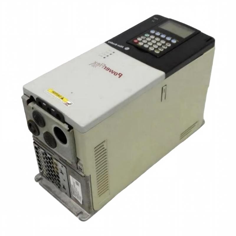
Allen Bradley 20BD022A0AYNANC0 PowerFlex 700 Overcurrent Fault Troubleshooting Guide
Time:2026-10-26 Browse: 2
Identifying PowerFlex 700 Overcurrent Faults Under Load
Allen Bradley 20BD022A0AYNANC0 PowerFlex 700 AC Drive overcurrent faults during acceleration or loaded operation should be investigated by comparing the fault timing, motor current, mechanical load, and drive configuration. A trip under heavy load does not automatically indicate a defective drive. The same symptom can result from an obstructed machine, incorrect motor data, output-cable problems, or an acceleration profile that demands excessive torque.
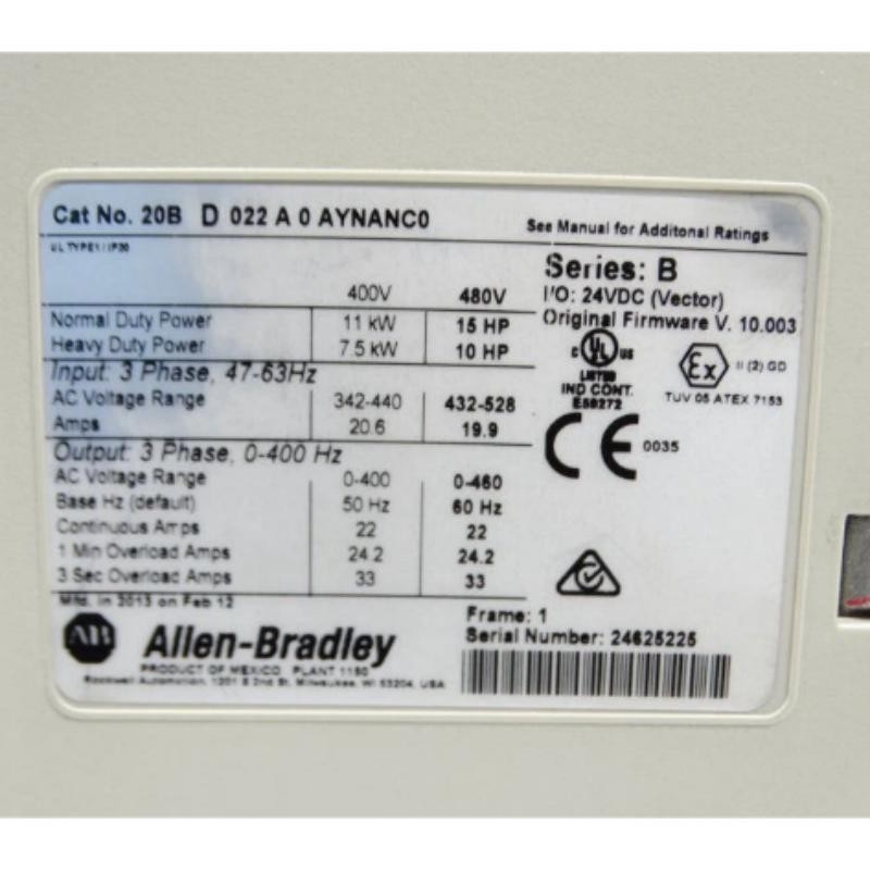
This model has a nominal output current rating of 22 A, but the acceptable operating current depends on the configured duty rating, application, ambient conditions, and manufacturer specifications. A single current reading cannot establish whether the drive is operating correctly.
Reading PowerFlex 700 Fault History Before Resetting
The first priority in Fault Diagnosis is to preserve the exact fault code and operating conditions. Record whether the event occurs immediately after power-up, when a start command is issued, during acceleration, or after the motor has reached operating speed.
The timing helps separate several possible causes:
Immediate trip: Investigate wiring faults, motor-circuit shorts, and the precise fault indication.
Trip during acceleration: Examine load inertia, acceleration settings, motor data, and current behavior.
Trip during steady operation: Check sustained mechanical load, motor cooling, supply conditions, and the applicable fault history.
Intermittent trip: Look for changes in loading, loose connections, thermal conditions, or disturbances associated with the machine cycle.
Do not repeatedly reset the drive before collecting the evidence. Resetting without recording the original indication can remove useful diagnostic context.
A Loaded Conveyor Fault: PowerFlex 700 Diagnostic Reasoning
Consider a hypothetical field case in which a conveyor starts successfully when empty but trips as products accumulate on the belt. The initial evidence points toward a condition that changes with mechanical load.
The engineer should first inspect the conveyor for binding, excessive friction, obstructed rollers, or an overloaded mechanism. Next, compare the motor nameplate data with the configured drive parameters and review the acceleration time.
Suppose a clamp-meter reading or suitable drive measurement shows current increasing from 5 A during unloaded operation to 12 A during loaded startup. These figures are illustrative, not measurements from an actual repair or guaranteed operating values for this catalog number. Whether 12 A is acceptable depends on the motor rating, measurement method, and operating conditions.
If the current increase coincides with a sudden mechanical load, investigate the machine before replacing drive components. If the load is normal but current rises abnormally, examine the motor circuit, parameter configuration, and recorded fault information.
The diagnostic principle is straightforward: identify what changes immediately before the trip, then test the most plausible causes in a controlled sequence.
Corrective Measures for 20BD022A0AYNANC0 Motor Overcurrent
Once the cause is supported by evidence, apply the appropriate correction.
If the motor parameters are incorrect, enter the verified nameplate values and repeat a controlled test. If the mechanical load is excessive, correct the mechanical condition before restarting. If the acceleration ramp is unsuitable, adjust it within the machine's operating requirements and the manufacturer's recommendations.
Inspect motor cables and connections for damage, contamination, and loose terminations. Insulation testing must be performed using an approved procedure with the drive electronics disconnected as required by the manufacturer. Never apply an insulation tester directly through connected drive electronics unless the manufacturer's procedure explicitly permits it.
If the fault persists after the supply, wiring, motor, loading, and configuration have been checked, qualified service personnel should evaluate the drive's internal power components. An overcurrent indication alone is not sufficient evidence that an IGBT or gate-drive circuit has failed.
PowerFlex 700 DC Bus Overvoltage During Deceleration
A separate failure pattern occurs when the drive runs normally but trips while stopping a high-inertia load. In this situation, investigate the exact fault indication and DC bus behavior rather than assuming that the same cause explains every drive trip.
During deceleration, a rotating motor can return energy to the drive. If the energy cannot be dissipated or managed adequately, the DC bus voltage may rise and trigger an overvoltage fault.
The 20BD022A0AYNANC0 includes a braking IGBT but does not include a factory-installed braking resistor. If the application requires dynamic braking, verify the braking design, resistor compatibility, wiring, and drive parameters against the manufacturer's documentation.
A longer deceleration time may be appropriate for some applications, but it is not a universal solution. The correct response depends on the machine's stopping requirements, inertia, safety design, and fault evidence. Never disable required safety functions to prevent a nuisance trip.
PLC Controller and PowerFlex 700 Start-Command Fault Diagnosis
Not every failure to operate is an internal drive fault. If the PowerFlex 700 displays no active fault but does not respond to a PLC Controller, investigate the command path and System Configuration.
For a hardwired interface, compare the PLC output state with the actual drive input state. Confirm the control voltage, terminal assignments, common reference, and selected command source. For communication-based control, verify that the appropriate communication hardware is installed and that command and status data are mapped correctly.
A useful test is to compare the requested command, the command received by the drive, and the reported running state. A mismatch between these signals helps narrow the investigation to the PLC logic, electrical interface, communication configuration, or drive operating state.
Do not bypass interlocks or force outputs without an approved test procedure. Unexpected motor movement can create serious mechanical hazards.
Repair Confirmation and Return-to-Service Testing
After corrective work, preserve the original fault record and document the changes made. Clear the fault according to the manufacturer's procedure, then reproduce the original operating condition under controlled circumstances.
Confirm that the drive starts, accelerates, operates under representative load, and stops without recurring faults. Compare current and voltage measurements against the applicable equipment specifications rather than relying on generic thresholds.
If an internal component failure is confirmed, use qualified service personnel and approved repair procedures. Record the diagnosed cause, replacement components if applicable, final parameter settings, and post-repair test results.
A successful Troubleshooting process establishes a defensible root cause and verifies that the correction works under the conditions that originally produced the failure. A single successful restart is not sufficient evidence of a completed repair.
Long-Tail Keywords for PowerFlex 700 Fault Diagnosis and Repair
This guide covers Allen Bradley 20BD022A0AYNANC0 overcurrent troubleshooting, PowerFlex 700 acceleration faults, 480 V AC Drive fault diagnosis, PowerFlex 700 DC bus overvoltage during deceleration, Allen Bradley drive not responding to PLC commands, variable frequency drive motor current analysis, and PowerFlex 700 repair verification. Accurate diagnosis depends on the actual fault code, operating history, measured electrical conditions, and the specific drive configuration.