Allen-Bradley 100S-D210EA22BC Safety Contactor Installation and Commissioning Guide
Time:2026-10-23 Browse: 3
Allen-Bradley 100S-D210EA22BC Safety Contactor Installation Overview
The Allen-Bradley 100S-D210EA22BC Safety Contactor requires correct power-circuit wiring, control-coil compatibility, and safety-feedback integration to operate reliably in industrial motor-control systems. Incorrect coil voltage, improperly connected feedback contacts, or unsuitable motor-load protection can prevent the contactor from performing its intended switching and monitoring functions.
The 100S-D210EA22BC belongs to the Bulletin 100S-D safety contactor family. Product documentation identifies a three-pole main contact arrangement, an electronic coil, and auxiliary contacts intended to support safety-circuit monitoring. The exact electrical ratings and terminal assignments should be verified against the manufacturer's documentation for this specific catalog number.
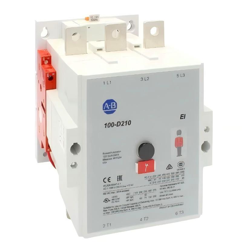
Allen-Bradley 100S-D210EA22BC Safety Contactor Applications
This safety contactor can be incorporated into appropriately engineered motor-control and machine-safety systems where controlled disconnection of electrical power is required. Typical design considerations include motor switching, emergency-stop circuits, protective interlocks, and feedback monitoring.
A safety contactor is not a complete safety system by itself. Its protective function depends on the surrounding safety relay or safety controller, circuit architecture, contactor arrangement, feedback logic, and validated risk-reduction design.
Before installation, establish whether the application requires one contactor or a monitored arrangement using multiple contactors. The selection must follow the machine's risk assessment and applicable safety requirements.
Preparing the Allen-Bradley 100S-D210EA22BC for Installation
Inspect the device and panel before mounting. Confirm the complete catalog number, inspect the terminals and housing for damage, and check that the available enclosure space accommodates the contactor and required accessories.
The installation preparation should cover:
Control supply: Verify the electronic coil's rated voltage and permitted operating range using the exact model documentation.
Power circuit: Confirm the motor's rated current, starting characteristics, utilization category, and expected switching frequency.
Protection coordination: Select suitable short-circuit protective devices according to the manufacturer's approved coordination tables.
Safety feedback: Identify the normally open and normally closed auxiliary contacts and confirm which contacts are specified for safety monitoring.
Environmental conditions: Check ambient temperature, enclosure protection, mounting orientation, and the required clearances.
Isolate all relevant power sources and verify the absence of hazardous voltage before installation or wiring work. Only qualified personnel should perform the electrical installation.
Allen-Bradley 100S-D210EA22BC Power and Control Wiring
The three main poles must be wired according to the approved circuit diagram, with conductor sizes, terminal preparation, and tightening torque selected from the applicable installation instructions.
Keep the control circuit clearly separated from the main power circuit in the wiring documentation. Verify that the control supply matches the coil specification before energizing the contactor. Do not infer coil compatibility from the nominal voltage of another 100S-D model.
The auxiliary contacts require particular attention. In safety applications, the designated normally closed mirror contacts are used to monitor the contactor's state through the safety circuit. Their correct connection allows the safety controller to detect certain failures, including a main contact that remains closed when the contactor is commanded to open.
Use the manufacturer's terminal diagram to identify the correct feedback terminals. Incorrect auxiliary-contact wiring can cause startup inhibition, misleading status indications, or ineffective fault monitoring.
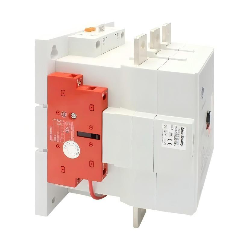
Allen-Bradley 100S-D210EA22BC Setup and Commissioning Procedure
Commissioning should verify the power circuit, control circuit, and safety-monitoring function independently before the machine is returned to service.
Power-circuit inspection: Confirm conductor connections, protective-device selection, and the specified terminal torque. Check for loose strands, damaged insulation, or signs of overheating.
Coil operation: Verify the control supply at the documented measurement points. Confirm that the contactor pulls in and releases consistently when commanded.
Feedback validation: Operate the contactor under the approved test procedure and verify that the monitored auxiliary contacts change state as expected. Confirm that the safety relay or controller recognizes the corresponding state.
Emergency-stop testing: Test the complete safety function under controlled conditions. Verify that the intended power-disconnection function occurs and that a failure to achieve the required contactor state prevents an unsafe restart.
Documentation: Record the catalog number, relevant electrical measurements, safety-test results, and any corrective actions.
Allen-Bradley 100S-D210EA22BC Commissioning: Engineering Verification
Consider a representative motor-control installation in which the contactor energizes correctly, but the machine safety controller does not permit a restart after an emergency-stop test.
The appropriate response is to examine the feedback circuit rather than immediately replace the contactor. The engineer checks the auxiliary-contact terminal assignments, the safety-controller input state, and the contactor's mechanical return to its de-energized position.
If the contactor releases correctly but the feedback input remains in the wrong state, the problem may be related to wiring, a faulty auxiliary contact, or the safety-controller configuration. If the main contacts do not open as required, the investigation must instead address a potentially serious switching failure.
This is an illustrative commissioning scenario, not a claim of a documented failure involving a particular 100S-D210EA22BC unit.
Allen-Bradley 100S-D210EA22BC Installation Acceptance
The installation is ready for handover only after the applicable electrical and functional safety checks have passed. Confirm that the contactor operates within its specified ratings, the feedback circuit behaves correctly, and the complete machine safety function meets its validated requirements.
Retain the wiring diagram, test results, protective-device details, and relevant configuration records. These records provide a baseline for future Troubleshooting, Fault Diagnosis, and preventive maintenance.