Allen-Bradley MPL-B880C-SJ74AA Servo Motor Installation Guide (Brake Wiring & Commissioning)
Time:2026-10-20 Browse: 0
Allen-Bradley MPL-B880C-SJ74AA Servo Motor Installation Requirements
The Allen-Bradley MPL-B880C-SJ74AA servo motor requires correct mechanical mounting, compatible drive configuration, and proper brake-circuit integration for reliable motion control. This MP-Series low-inertia brushless AC servo motor is rated for 460 V-class applications and 1500 rpm, with a 265 mm frame, 203.2 mm magnet stack, single-turn high-resolution encoder, and a 24 V DC holding brake. The model also features a keyed shaft extension and a right-angle SpeedTEC DIN connector.
Unlike the closely related MPL-B880C-SJ72AA, which has no brake, the SJ74AA version includes a 24 V DC brake. This difference directly affects installation planning, especially where a vertical axis or suspended load must be held when motor torque is removed.
Mechanical Alignment Before Installing the MPL-B880C-SJ74AA
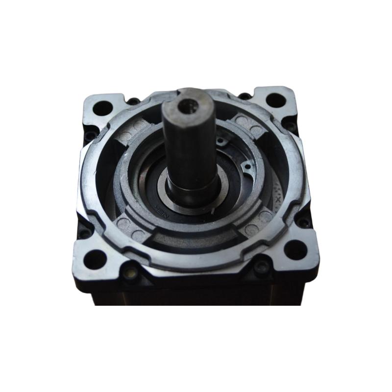
Inspect the motor housing, shaft, mounting face, and connector before attaching the motor to the machine. Confirm that the mounting dimensions and shaft interface match the coupling or gearbox specified in the mechanical design.
The keyed shaft must engage correctly with the mating component. Do not force the coupling into position or use the mounting bolts to compensate for shaft misalignment. Excessive radial or axial loads can damage the motor bearings and affect positioning accuracy.
For vertical or gravity-loaded applications, determine how the load will be supported during installation and maintenance. Although the motor has a holding brake, the brake should not be treated as a substitute for required mechanical safety supports.
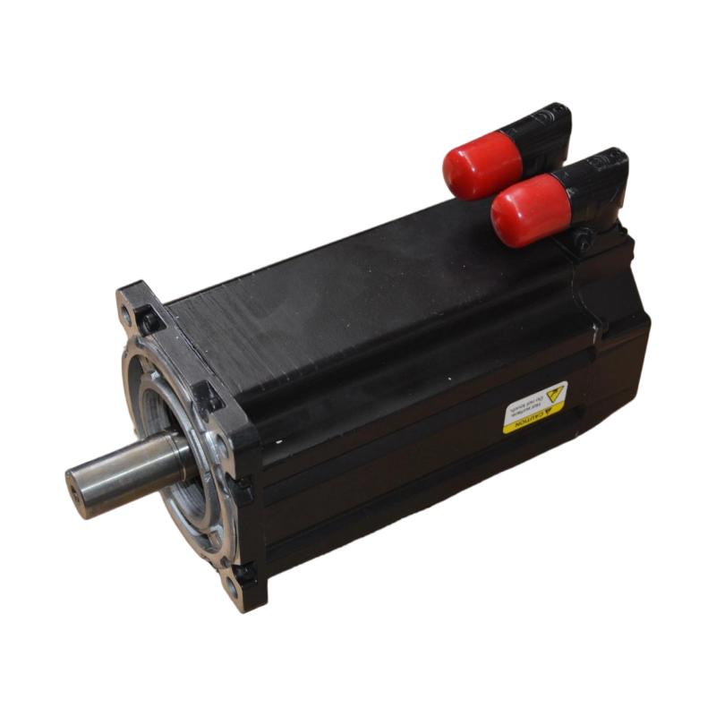
Brake Circuit and Electrical Wiring for the Allen-Bradley MPL-B880C-SJ74AA
The 24 V DC brake requires a compatible control circuit and the correct motor cable arrangement. Verify the brake wiring, connector pin assignments, and drive-side control method using the documentation for the exact motor and servo drive combination.
Do not assume that the motor brake is controlled through the same conductors as the motor phases or encoder feedback. Confirm the approved wiring diagram before making connections.
During installation, isolate the power supply and follow the drive manufacturer's requirements for stored-energy discharge. Inspect motor power, feedback, and brake connections for correct termination, secure locking, and appropriate cable routing. Keep feedback wiring protected from interference generated by motor power conductors and switching equipment.
The brake's release and engagement sequence must also be checked. Applying the wrong sequence can allow the load to move unexpectedly or cause the brake to resist motion while the motor is producing torque.
Configuring the MPL-B880C-SJ74AA in the Servo Drive
The drive configuration should identify the exact motor model and its feedback characteristics. Confirm the 460 V-class supply compatibility, 1500 rpm rated speed, single-turn encoder configuration, and brake-related parameters supported by the selected drive.
Set the operating speed, acceleration, deceleration, torque limits, and following-error limits according to the actual machine design. These settings cannot be determined from the motor model alone because load inertia, transmission stiffness, and process requirements vary by application.
Where supported by the drive, verify the brake control output and the required timing between brake release, torque establishment, and motion enable. Use the manufacturer's specified sequence rather than assigning arbitrary delays.
Commissioning the Allen-Bradley MPL-B880C-SJ74AA Brake and Motion System
Initial commissioning should confirm the electrical, feedback, and mechanical systems independently before testing the complete axis.
With the load safely secured, verify that the drive recognizes the motor and encoder and reports no unresolved configuration faults. Test the brake circuit according to the manufacturer's procedure and confirm that the brake releases when commanded under the specified conditions.
Next, perform a low-speed movement test within a safe travel range. Monitor commanded position, actual position, motor current, and following error. Confirm that the brake does not remain engaged during motion and that the axis does not move unexpectedly during transitions between enabled and disabled states.
For a vertical axis, verify the holding sequence under a controlled test plan. Do not remove motor torque while relying solely on an unverified brake to support a suspended load.
Field Validation and Installation Acceptance
A representative commissioning scenario involves a vertical positioning axis that moves correctly after startup but drifts slightly when the drive is disabled. The engineer should verify whether the brake engages as intended, inspect the brake-control sequence, and determine whether the observed movement comes from mechanical backlash, brake response, or an external load.
This is an illustrative engineering scenario, not a documented field repair for this specific motor. The final acceptance criteria must come from the machine design and applicable manufacturer specifications.
Record the motor catalog number, drive configuration, brake-control settings, encoder status, and motion-test results. The axis should enter production only after both motion performance and load-holding behavior have been verified.
Allen-Bradley MPL-B880C-SJ74AA Installation Guide: Long-Tail Checks
For Allen-Bradley MPL-B880C-SJ74AA servo motor installation, 24 V DC brake wiring, and servo drive commissioning, the most important checks are exact model identification, brake compatibility, mechanical alignment, and correct motion sequencing.
The SJ74AA brake option must be included in the System Configuration and commissioning documentation. Verify all electrical connections and brake operating requirements against the applicable Rockwell Automation manuals before enabling the machine.