Schneider 140ACO13000C Analog Output Module Installation Guide (Wiring & Setup)
Time:2026-10-19 Browse: 0
Schneider 140ACO13000C Installation Requirements for Modicon Quantum PLC Systems
The Schneider 140ACO13000C analog output module requires correct rack positioning, current-loop wiring, and channel configuration to deliver reliable control signals to field instruments. Designed for the Modicon Quantum automation platform, this eight-channel PLC Module supports configurable current outputs, including 4–20 mA, 0–20 mA, and 0–25 mA ranges. Before commissioning, engineers should verify the selected output range, external loop supply, and receiving-device compatibility against the manufacturer's specifications.
Unlike a digital output that switches between discrete states, the 140ACO13000C converts PLC output data into continuous current signals. A mismatch between the program's scaling and the configured output range can therefore produce an incorrect valve position, drive reference, or process-control command even when the PLC reports normal operation.
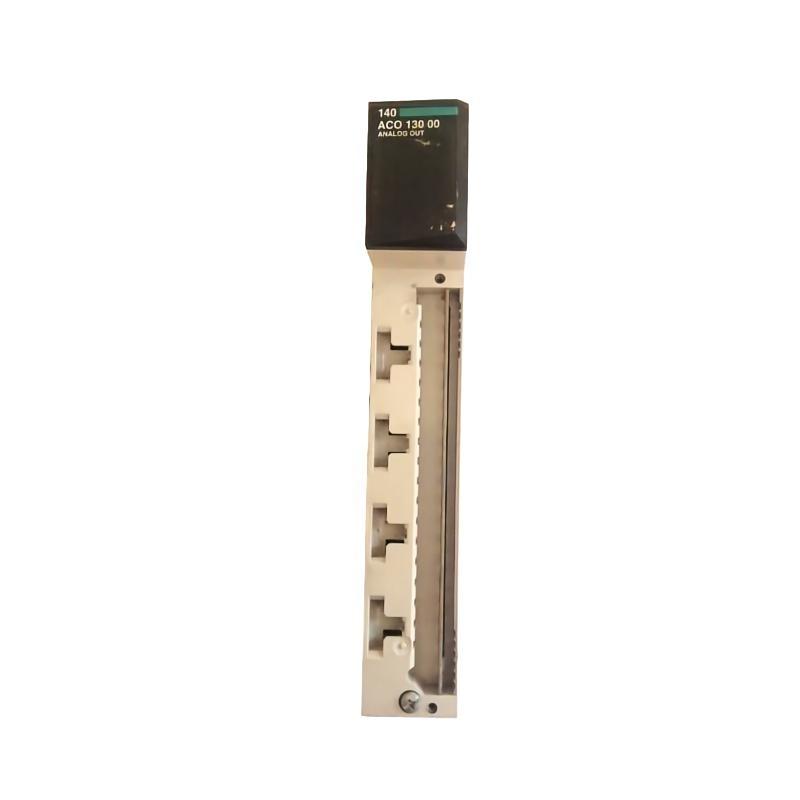
Preparing the Schneider 140ACO13000C Hardware and System Configuration
Before installation, confirm that the existing Modicon Quantum rack and controller configuration support the module. Review the hardware catalog entry, rack slot assignment, I/O address allocation, and approved project documentation.
The 140ACO13000C requires eight output words and an external loop supply within its specified 6–30 V DC range. Its published specifications include a typical absolute accuracy error of ±0.2% of full scale at 25°C and an update time of 5 ms. These values provide useful commissioning references, but they do not replace the need to verify the complete field circuit.
Prepare the module wiring diagram, field-device specifications, a suitable digital multimeter, and the approved electrical isolation procedure. Check whether the required terminal block and field wiring accessories are available for the installation.
Installing the Schneider 140ACO13000C and Checking Current-Loop Wiring
Install the module in the designated rack position according to the manufacturer's instructions. Isolate the equipment as required and use appropriate electrostatic-discharge precautions when handling the module.
During field wiring, verify each output channel's signal conductor and RETURN connection against the correct terminal diagram. The module documentation identifies the RETURN terminals as internally common. Consequently, the wiring arrangement must be checked against the intended circuit rather than assuming that each return is electrically independent.
Keep analog signal cables away from high-current switching conductors where practical. Apply the specified shielding and grounding practices for the installation, and inspect terminal tightness and cable condition before energizing the circuit.
The external loop supply also requires attention. The supply must provide sufficient voltage after accounting for the module's internal voltage drop and the receiving device's requirements. A nominally correct power supply can still cause problems if the available voltage under load is insufficient.
Configuring Schneider 140ACO13000C Analog Output Channels
The channel configuration must match the field instrument and the PLC application's scaling logic. For example, a valve positioner designed for 4–20 mA should not be commissioned using an incorrectly configured 0–20 mA range.
The module supports the following documented signal representations:
| Output range | Digital count range |
|---|---|
| 4–20 mA | 0–4095 |
| 4–20 mA | 0–16000 |
| 0–20 mA | 0–20000 |
| 0–25 mA | 0–25000 |
These count ranges are alternatives, not interchangeable settings. Verify the selected representation in the project and use the corresponding conversion formula in the PLC program.
For a linear 4–20 mA configuration using 0–16000 counts, a command of 50% corresponds to 8000 counts and an expected nominal output of 12 mA. This is a calculated reference value, assuming the selected range and scaling are correct.
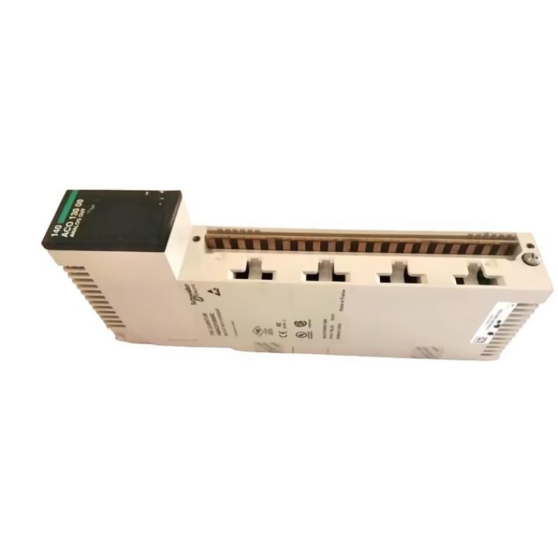
Schneider 140ACO13000C Setup and Commissioning Validation
Commissioning should establish that the configured PLC output produces the intended physical signal.
Start by confirming that the controller recognizes the module and that the configured rack slot and output address match the installed hardware. Review the Active, external-fault, and channel status indicators before proceeding with electrical tests.
Apply a safe test command under the approved commissioning procedure. Measure the output current using an appropriate method and compare it with the expected value calculated from the configured range. Then verify that the receiving instrument responds correctly.
For example, during a controlled valve test, commands of 25%, 50%, and 75% in a linear 4–20 mA configuration should nominally produce 8 mA, 12 mA, and 16 mA, respectively. Confirm that these test points are safe for the connected process and permitted by the field-device specifications.
If the measured current does not match the command, investigate the scaling, loop supply, and wiring before suspecting a hardware fault. Record the test results and final System Configuration so that future maintenance personnel can reproduce the verification.
Long-Tail Installation Checks for the Schneider 140ACO13000C Module
For Schneider 140ACO13000C installation, analog output wiring, and Modicon Quantum PLC commissioning tasks, the critical objective is to verify the entire signal path from the PLC program to the field instrument.
The module is ready for operational use only after the channel configuration, measured output, and field-device response agree with the approved engineering design. Any unresolved mismatch should be investigated before the output is released to automatic control.