Allen-Bradley MPL-B680H-SJ72AA Servo Motor Installation and Commissioning Guide
Time:2026-10-16 Browse: 3
Allen-Bradley MPL-B680H-SJ72AA Servo Motor Installation Requirements
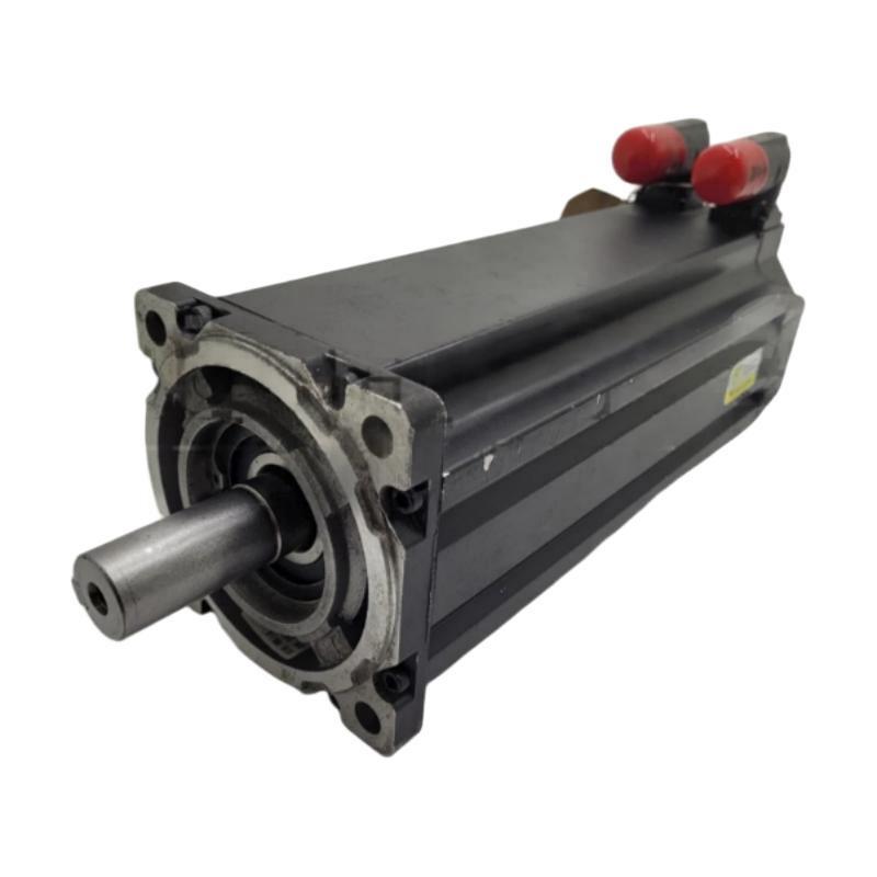
The Allen-Bradley MPL-B680H-SJ72AA servo motor requires compatible 460 V-class servo drive hardware, correct feedback configuration, and precise mechanical alignment for reliable operation. This MP-Series low-inertia brushless servo motor features a 215 mm frame, 203.2 mm magnet stack length, 3500 RPM rated speed, a single-turn high-resolution encoder, and a keyed shaft extension. It is supplied without a holding brake, making load-holding requirements an important consideration during machine design and commissioning.
Before installation, confirm that the motor's catalog number matches the machine drawings and the selected drive's supported motor configuration. A motor can be mechanically compatible with an existing installation yet still require different feedback settings or electrical connections.
Preparing the MPL-B680H-SJ72AA for Mechanical Installation
Inspect the motor housing, mounting flange, shaft keyway, and SpeedTEC DIN connector before mounting. Check for impact damage, corrosion, contamination, or damaged connector contacts. Verify that the mounting surface is clean and that the coupling or gearbox matches the shaft dimensions.
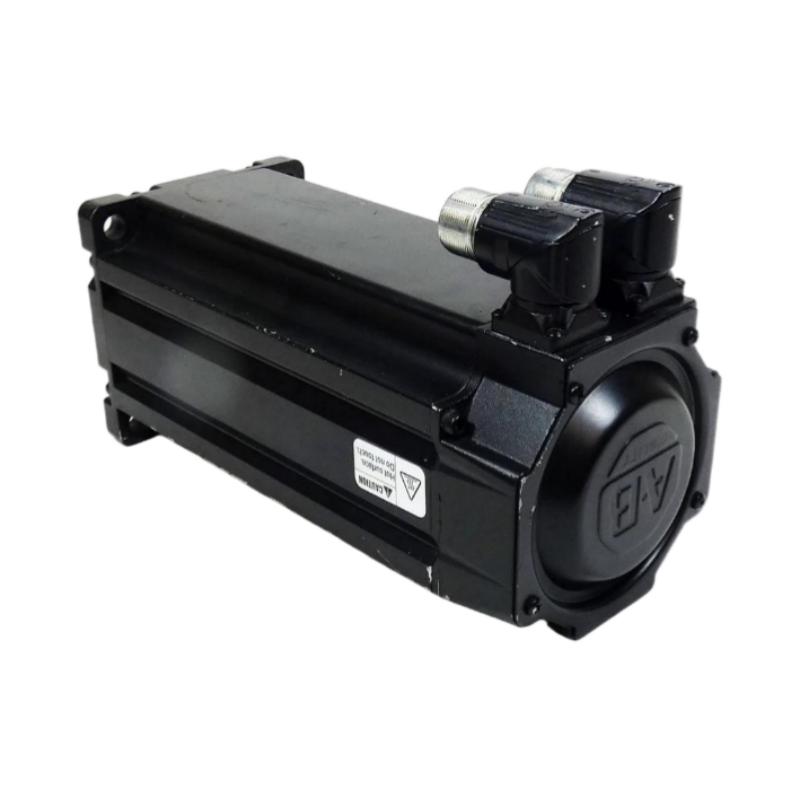
The motor uses a right-angle SpeedTEC DIN connector that can be rotated through 180 degrees according to the manufacturer's instructions. Position the connector to provide sufficient cable clearance without exceeding the permitted bend radius or placing excessive force on the connector.
The installation team should prepare the following:
The MPL-B680H-SJ72AA servo motor and compatible servo drive.
Approved motor power and feedback cables.
The machine mounting hardware and shaft coupling.
The applicable Rockwell Automation installation documentation.
Electrical isolation equipment and the approved commissioning procedure.
Do not use the motor shaft or connector as a lifting point. Confirm the motor's actual nameplate information before finalizing the replacement procedure.
Mechanical Alignment and Mounting Considerations
The MPL-B680H-SJ72AA uses an IEC metric mounting arrangement with free mounting holes of type FF. Verify the flange dimensions and mounting-hole pattern against the machine drawing before tightening the fasteners.
Shaft alignment is especially important in high-acceleration applications. Angular misalignment, excessive radial loading, or a poorly fitted shaft key can increase vibration and bearing stress. For belt-driven or gearbox-connected systems, compare the actual shaft loads with the manufacturer's allowable load specifications at the intended operating speed.
After mounting, rotate the mechanism manually only when the system is safely isolated and the machine design permits it. Check for unexpected resistance, coupling interference, and mechanical binding before applying power.
Because this motor has no integral holding brake, vertical axes and gravity-loaded mechanisms require a separately engineered load-holding solution where necessary. Do not assume that the servo drive alone will safely hold a suspended load during a power interruption.
Electrical Wiring and Feedback Configuration
The MPL-B680H-SJ72AA belongs to the 460 V-class MP-Series motor family and uses a single-turn high-resolution encoder. Confirm that the selected drive supports the feedback interface and the exact motor catalog number.
Motor power, feedback, grounding, and cable shielding must follow the manufacturer's wiring instructions. Keep feedback wiring appropriately separated from motor power conductors to reduce electromagnetic interference. Inspect connector engagement and cable condition before enabling the drive.
During System Configuration, verify:
The selected motor catalog number.
The supported feedback type and drive firmware compatibility.
Motor direction and position feedback settings.
Current, speed, acceleration, and other application limits.
The machine's response to loss of power or drive disable.
Do not copy parameters from another MP-Series motor solely because the frame size is the same. Differences in feedback, brake options, and motor characteristics can affect the commissioning procedure.
Setup and Commissioning of the Allen-Bradley Servo Motor
The Setup / Commissioning process should begin with the drive's motor identification and diagnostic checks. Confirm that the drive recognizes the intended motor and that no unresolved feedback or configuration faults remain.
The rated speed is 3500 RPM, but initial commissioning should use a conservative speed and acceleration suitable for the machine. Clear the movement area, secure the driven load, and follow the site's machine-safety procedure before enabling motion.
Run a low-speed test and observe the commanded direction, actual position, speed response, and motor current. If the axis moves in an unexpected direction or the feedback response is inconsistent, stop the test and investigate the configuration before proceeding.
Record the motor identity, drive model, configuration revision, and observed commissioning results. These records establish a baseline for subsequent maintenance and Troubleshooting.
Field Example: Investigating Abnormal Vibration During Commissioning
Consider a representative commissioning scenario in which the MPL-B680H-SJ72AA operates but produces more vibration than expected after coupling to a gearbox.
Replacing the motor immediately would be premature. The engineer first checks the mounting flange, coupling alignment, shaft key fit, and gearbox condition. Vibration is then measured at a consistent location and operating speed, with the result compared against the machine's acceptance criteria or an established baseline.
If vibration changes significantly after correcting alignment, the mechanical installation becomes a stronger candidate for the root cause. If vibration persists, the investigation should include the driven load, bearings, mounting rigidity, and motor-drive tuning.
This is an illustrative engineering scenario, not a documented customer repair. No unmeasured vibration value or verified improvement is claimed.
Final Validation of the MPL-B680H-SJ72AA Installation
Before releasing the machine, verify stable feedback, correct rotation, acceptable vibration, and reliable operation across the approved test range. Confirm that the absence of an integral holding brake has been addressed wherever the application requires mechanical load retention.
A complete Allen-Bradley MPL-B680H-SJ72AA Servo Motor Installation Guide should cover drive compatibility, mechanical alignment, feedback wiring, System Configuration, and controlled motion validation. Keeping these checks in the commissioning record helps engineers distinguish installation problems from later electrical or mechanical faults.